IT Standard for Factory Infrastructure
Version: 1, effective date: 01-Oct-2021
Contents
1 Standard description
This document will define required networking, server equipment, hardware installations, etc – on the production area (cabinets/computes), finished goods warehouse (cabinets/computes), server rooms, virtual infrastructure, and servers related to T&T
2 Document objectives and benefits
2.1 Objectives
Objectives of the document are:
- Identify the element of IT infrastructure in the scope of the T&T process at the factory
- Set requirements for the IT infrastructure element based on the JTI IT standards and policies
2.2 Benefits
The document helps to identify the readiness of factory IT infrastructure for T&T implementation.
3 Definitions
| Abbreviation / Term | Explanation |
|---|---|
| Cold backup | Also known as a static backup. Here, the database operations are entirely stopped, and then the backup is performed. |
| Hot backup | Also known as a dynamic backup. It is performed in near real-time when the systems are up and running, and new data is continuously generated or captured. |
| Data retention policy | Defines persistent data and records management for meeting legal and business data archival requirements. |
| Fracture Code | A company that provides T&T equipment and systems for the production lines. |
| WMS | Warehouse Management System – a solution which is used for the management of warehouse operations and processes. |
| Scanner | Hands-free scanner with the ability to read 1D and 2D code on labels. Scanners can be connected to the workstation via USB/Bluetooth/Wireless. |
| NCC | Network & Communication Center |
| DC TA | Data Center Technical Architecture |
| IACS | Industrial Automation & Control Systems, refers to all the components (PLCs, SCADA, HMI, etc.) that are integrated into critical infrastructures and industrial production establishments. |
Please refer to IT Glossary in the IT P&P portal for further definitions.
4 Roles & Responsibilities
The ARCI tables below operate with the following abbreviations:
Accountable: Approves the activity or recommendations from a person or team.
Responsible: Responsible to do the work associated with an activity, either by completing personally or through sole accountability for a team’s output.
Consulted: Reviews the output of an activity and provides input, but has no approval authority. Provides support to activity and may be consulted by the team during the course of the activity.
Informed: Is informed about activities to aid in planning own work.
4.1 Process Stakeholders
| # | Activity | BTS T&T | NCC | GDC T&T | GTC-DC-TI | GTC-DC-TA | GTC-DC-SD | Factory |
|---|---|---|---|---|---|---|---|---|
| 1 | Define and maintain standard | A/R | C | C | I | |||
| 2 | Apply the document in the T&T Implementation projects | R/A | R |
4.2 Infrastructure Stakeholders
| # | IT infrastructure element | BTS T&T Service | NCC | GDC T&T | GTC-DC-TI | GTC-DC-TA | GTC-DC-SD | Factory |
|---|---|---|---|---|---|---|---|---|
| 1 | Server rooms | C | C | R/A | ||||
| 2 | Server hardware infrastructure | C | R/A | |||||
| 3 | Server software | I | C | R/A | I | |||
| 4 | Network | I | R/C | A | ||||
| 5 | IACS Network | I | C/I | I | R/A | |||
| 6 | Cloud network | I | R/A | R | I | |||
| 7 | Fracture Code equipment | I | C/I | R/A | ||||
| 8 | JTI office station | I | I/C | R/A | ||||
| 9 | WMS | I | C | I/C | R/A |
5 IT Standard for Factory Infrastructure
The standard has defined the root elements of T&T IT Infrastructure their requirements, standards, and configuration.
5.1 T&T IT Infrastructure Elements
Following IT infrastructure elements on Factory to build T&T IT infrastructure on the side:
-
JTI network – it combines all elements of network infrastructure which used to organize network connection for JTI IT resources such as servers, desktops, switches, and any others with internal resources (intranet) and external (Internet) connection.
-
Server infrastructure – this part described hardware resources which are used to build virtual server infrastructure. This part is under the control of the DC infrastructure team and should be build based on the JTI standards.
-
Server rooms – this point describes requirements for the rooms where placed server hardware infrastructure.
-
IACS Network – this point describes a network dedicated to IACS Network Cells that should or could connect to JTI CORP Network or external network or resources.
-
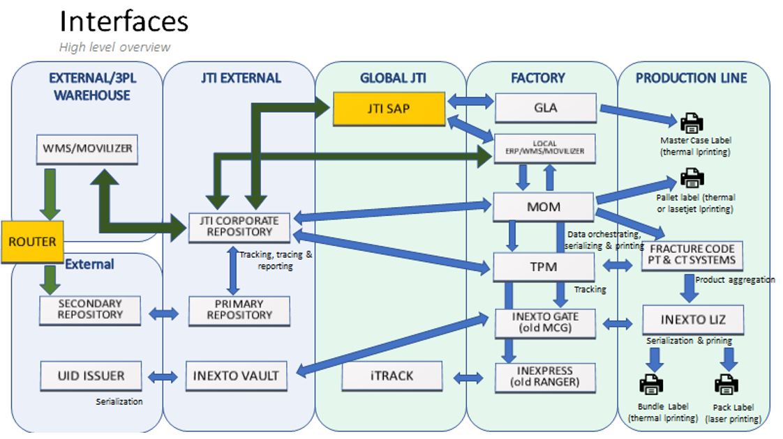
Fracture Code station – this is an element of the production line which is used to control the packaging process which is provided and supported by Fracture Code company. This equipment is used to place elements of the T&T system as Liz, COG, and finish goods aggregation. This equipment is placed inside the same Network Cell as other components that support the T&T process and its requirements such as LAS, LCE, and ATD.
-
JTI office workplace – desktop, laptop, or mobile PC which is used for organization workplaces for employees. This equipment is used for the installation of T&T elements for end-users or access to T&T Web resources.
-
Warehouse Management Solution – application is used at Finish Good Factory warehouses for registration shipment and delivery operations for Finish Goods.
-
T&T finished goods scanning station – this station is used for scanning finished goods and processing them to T&T solution at factory finish good warehouses. This is an optional element at present at the factory if warehouses are not covered by and WMS solution or this solution is not allowed to send data to T&T.
5.2 T&T IT Infrastructure Element Readiness
Availability and readiness of IT infrastructure elements should be identified based on the IT standards for the Factory infrastructure checklist. The checklist should be completed by Factory IT. Experts from other departments could be invited to the checklist preparation.
5.3 T&T IT Infrastructure Elements Requirements
6 Data Lake
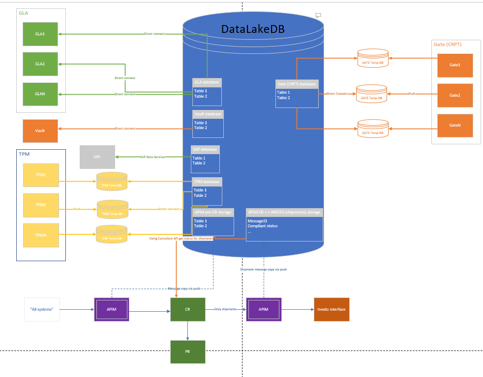
The proposed solution will consist of three separate data flow processes. The first process involves retrieving data stored in the Data Lake in the form of APIM messages through Synapse queries and temporarily storing the data, maintaining its original sequence, in a SQL database. The second flow which will read data from the temporary storage and upload to the data messages. The final data flow process involves extracting transactional data.
6.1 TPM Implementation of Data Lake
Data Lake provides a centralized repository for ingesting and storing data from various sources, making it easier to do all types of processing and analytics across multiple platforms and languages.
TPM Data Lake intermediate databases that are named in DLTPMXXX format is used to store information from TPM. During Data Lake process, the information is updated from the intermediate database.
When TPM is installed in a new place, a new source is added to Data Lake system, and data is being transferred or pushed to Data Lake.
The creation of the intermediate DB is done on DevOps process of implementation of TPM. TPM Data Lake DB permissions can be accessed from IMP_IP004 TPM Implementation procedure.
Once this is implemented and the TPM is deployed and configured with the help of FractureCode, the intermediate database will begin to fill up with new information.
After these steps are completed Data Lake team should be advised. The team will create a new source within Data Lake to this new DB created and start transferring or pushing data from there. They confirm whether they have received data from the database and the configuration is complete.
When more tables or fields are added to Data Lake, Data Lake team should be advised to change the structure of the tables to continue pulling data from TPM DBs. In this case a new schema must be created with all the fields and tables in the DB.
6.2 GATE (CRPT) Implementation of Data Lake
Data Lake provides a centralized repository for ingesting and storing data from various sources, making it easier to do all types of processing and analytics across multiple platforms and languages.
When GATE (CRPT) is installed in a new place, a new source is added to Data Lake system, and data is being transferred or pushed to Data Lake.
GATE (CRPT) DB creation steps and permissions can be accessed from IMP_IP002 Gate Installation Procedure.
After these steps are completed Data Lake team should be advised. The team will create a new source within Data Lake to this new DB created and start transferring or pushing data from there. They confirm whether they have received data from the database and the configuration is complete.
When more tables or fields are added to Data Lake, Data Lake team should be advised to change the structure of the tables to continue pulling data from GATE (CRPT) DBs. In this case a new schema must be created with all the fields and tables in the DB.
6.3 GLA Implementation of Data Lake
Data Lake provides a centralized repository for ingesting and storing data from various sources, making it easier to do all types of processing and analytics across multiple platforms and languages.
For Data Lake to collect data from a new GLA database, we need to be sure that the new database has granted access for user Z_TAT_HARDENING_PROD.
Firewall settings should be used for Data Lake to limit IP ranges and allow strict access based on requirements.
TA and DCO DB Team can help by monitoring the SQL server performance during the extract.
When more tables or fields are added to Data Lake, Data Lake team should be advised to change the structure of the tables to continue pulling data from GLA DBs. In this case a new schema must be created with all the fields and tables in the DB.
6.3.1 Network
T&T solution is working with the following networks:
-
JTI CORP network
-
IACS Network
-
Cloud network
6.3.1.1 JTI CORP network
6.3.1.1.1 JTI background
JTI network should be built in appliance with JTI policy “Network and Communications Security (10.161)”. All exceptions must be identified documented and agreed upon with responsible teams.
6.3.1.2 IACS network
6.3.1.2.1 JTI background
Factory IACS network is built according to IACS Network Standard. Legacy IACS Network (Factory supported) should be used where the new design is not yet implemented. In this case, relevant roles and responsibilities will apply.
6.3.1.2.2 T&T standard
Since T&T infrastructure is critical for production and contains sensitive data, we need to ensure that there is a secured communication channel between system components. Production lines interact with the T&T Application servers via a number of ports and protocols which should be allowed on JTI network equipment.
By default, servers in each JTI location are placed in network VLAN 200. However, for T&T we have a special part of VLAN200 selected for T&T Servers. At each factory, this is a different part of VLAN200 and it must be recorded in technical documents located here. All IPCs (computers on the production line) should be connected to IACS Network according to requirements in GEPC10.400 – Network Cell standard.
In order to ensure that IPCs can properly communicate with the T&T systems we need to apply a communications template. This template is updated each time new communication channel needs to be established between T&T components. And then it is applied to all factories to have consistency across all JTI sites. The latest template can be found here. Remote access shall follow the standard “GEPC10.500 Remote service” (e.g. PCS Interco).
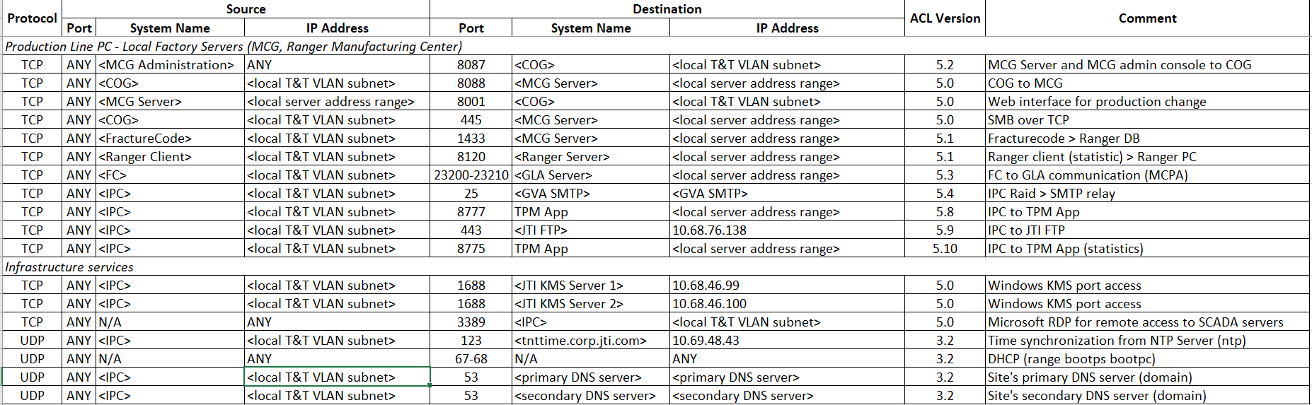
The necessary communication between hosts in IACS Network and Servers in JTI Corp should be enabled on Front Firewalls that connect IACS Network to JTI CORP Network. Policies will be documented on the NCC SharePoint.
6.3.1.2.3 Exception
All exceptions should be agreed upon with all stakeholders. To see the list of stakeholders, please check the “Infrastructure Stakeholders” table in the “Roles and Responsibilities” section of this document.
6.3.1.3 Cloud network
6.3.1.3.1 T&T standard
There is a number of externally hosted systems connection to which is essential for T&T environment to perform its functionality.
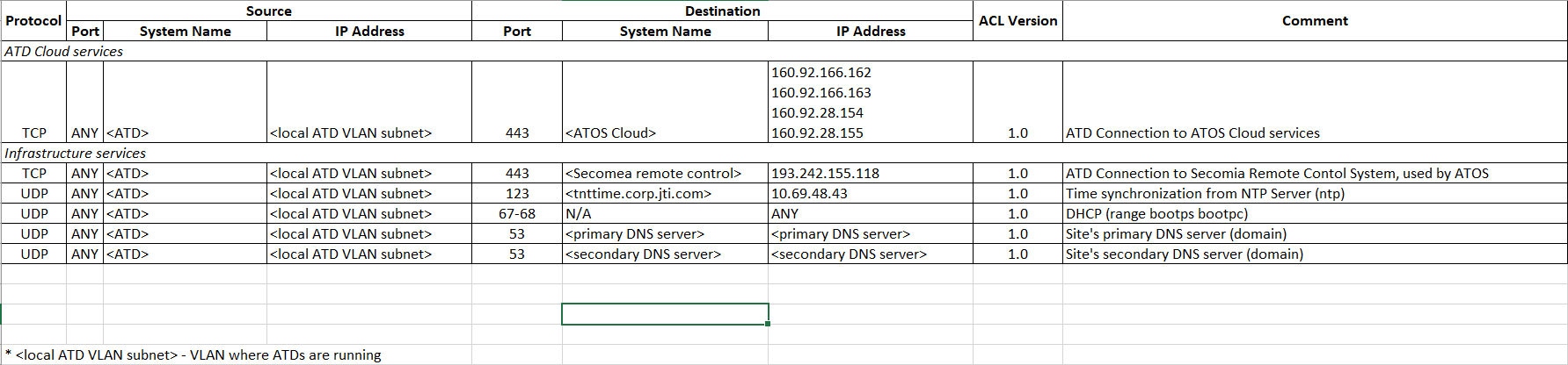
In order to build connection for such elements servers with T&T modules which required connection should be included into ATOS Connection policy (based on each server IP address) on local FortiGate and on Geneva FortiGate as well. This policy is updated through an operational change request whenever a server needs to be added/removed. The most recent list of servers allowed to connect to ATOS can be found here.
For Anti-Tampering devices (ATD) there is also a need to connect to ATOS cloud. Therefore, ATD’s should be connected in a special configuration so that communication with other components in the network cell can be restricted to the minimum required (see the proposed solution).
6.3.1.3.2 Exception
There is no possible exception.
6.3.2 Server Rooms
The factory should have at least two independent server rooms. The network topology should guaranty redundancy of network connections between server rooms in case of network issues with some network elements. All server rooms must correspond to the policy “IT Facility Physical and Environmental Security (10.009)” and standard “Data Center Physical and Environmental Security (10.115)”. These rooms should be located in different parts of the factory building with fully independent communications (power, ventilation system, cabling paths, fire protection system, etc.).
6.3.3 Servers Infrastructure
T&T server infrastructure is built based on several servers (GLA, TPM, MCG, Database) and they are critical part of T&T stable work. T&T server infrastructure can be different side by side based on site specific. In this case requirements should be separated on few parts;
-
Server hardware
-
Server software
-
General requirements
6.3.3.1 Server hardware
6.3.3.1.1 T&T hardware standard
Server hardware infrastructure is based on virtual machines solution and can be organize in two ways:
- Based on HCI (hyper-converged infrastructure)
- Based on 2 physical standalone servers.
TA will provide recommended solution taking into consideration requirements for Track and Trace and other systems used on site in total (like File Server, Print Server, local system) to keep one complex solution for all Servers.
Main files used to assess proper solution:
Calculator - to calculate resources required by Track & Trace applications, based on production lines quantity and Volume
AZ-HCI_Specifications.xlsx - tool used by TA to provide recommended solution and prepare hardware specification
Solutions comparison:
HCI - higher cost, higher performance, automatic redundancy - fast recovery solution. Solution can be used in each location.
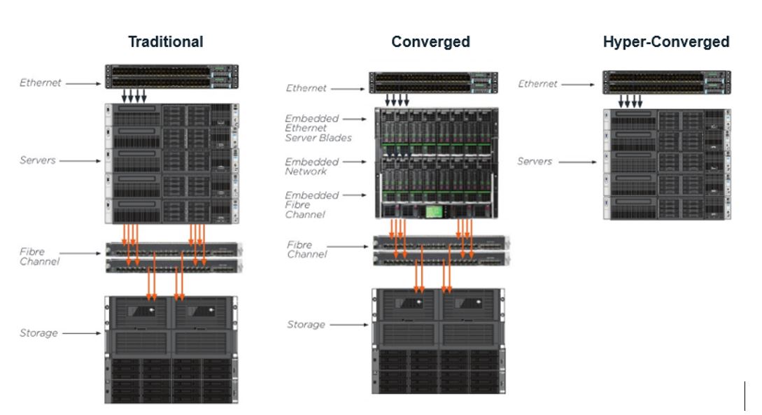
Standalone hosts - lower cost, performance adequate but max up to 10 Virtual hosts in total, manual redundancy, required involvement DCO team and more time for system recovery - up to 24 hours. Solution can be used only in small locations.
6.3.3.1.2 Exception
All exceptions should be agreed upon with all stakeholders. To see the list of stakeholders, please check the “Infrastructure Stakeholders” table in the “Roles and Responsibilities” section of this document.
6.3.3.2 Server software
Requirements to the server software are based on the T&T components requirements and can be changed in future.
6.3.3.2.1 JTI background
Standard server software described in the documents “Windows Server Configuration (10.110)”, “Microsoft SQL Server Configuration (10.120)”, “Linux Distribution (10. 147)”
6.3.3.2.2 T&T software standard
Requirements for the T&T components:
-
SQL servers cluster. This is a cluster of two virtual machines with SQL servers installed above the Windows server Operating System. Databases of each of the T&T systems are joined into Always-On Availability Groups and being accessed by the systems via DNS Aliases.
DNS Aliases naming convention is:
tat-<app>-db-<xxx>[-<ttt>].jti.comwhere:<app>stands for the application name<xxx>3 letter location code<ttt>3 letter location type code “RMC”, “RRP”, “EFH” or “OTP”.
Example:
tat-tpm-db-pet.jti.comortat-gla-app-gst-rmc.jti.com -
TPM application servers. 2 independent windows 2016 servers or later. Aim is to provide High Availability (HA) features for the TPM application. (Primary TPM application server, by default, acts as file witness for the SQL cluster. For locations without TPM solution is being developed to select another server to act as the file witness.)
-
GLA application servers. 2 independent windows 2016 servers. Aim is to provide High Availability (HA) features for the GLA application.
-
Gate/InexPress application servers. Gate and InexPress applications by default reside on the same Windows 2016 server. However, second server as also available for Gate and InexPress applications to provide HA features.
-
ALOHA HA Proxy load balancer. 2 clustered Linux-based load balancer servers which fulfil the HA feature for the T&T application servers. At the moment full testing of ALOHA Load Balancer has been conducted for TPM application servers and preliminary tests performed successfully for Gate.
- GLA application is being further developed to become compatible with HA standards.
- InexPress was excluded from the load balancing solution due to complexity and low level of possible advantages in using HA Proxy.
-
Optional TPM application server for Pre-Prod environment. Windows 2016 server without additional redundancy options.
-
Optional TPM Pre-Prod Database server. SQL server without additional redundancy options.
-
Primary GLA Server should be used by default as file witness for the SQL cluster
Current requirements directly depend on the T&T application and must be checked with GDC T&T Delivery centre team.
Please use the calculator to check resource requirements based on production details.
6.3.3.2.3 Exception
All exceptions should be agreed upon with all stakeholders. To see the list of stakeholders, please check the “Infrastructure Stakeholders” table in the “Roles and Responsibilities” section of this document.
6.3.3.3 General requirements
JTI uses Virtual Machines (VMs) in most cases. Virtualization platform is currently based on Microsoft Hyper Converged Infrastructure (HCI). The current standard required two fully separate HCI clusters located in each of the above-mentioned server rooms at a factory. This standard with two HCI clusters can provide higher sustainability to possible hardware issues. Please check the “Server hardware” section of this document for further details.
All the HCI server nodes are being patched and maintained per JTI standards in online mode and regularly. There is no impact to services during the planned maintenance of HCI cluster nodes.
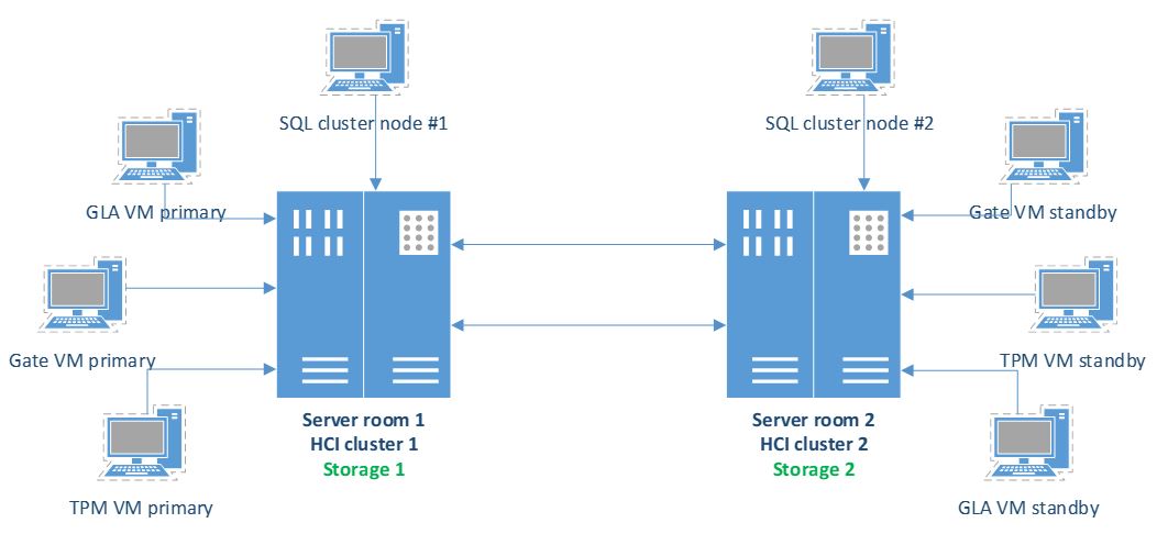
Factory server infrastructure example:
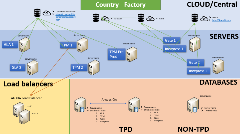
The schema above represents the full possible list of IT components that can be installed at a JTI factory for T&T systems.
6.3.4 Fracture Code Equipment
It is a part of production line and used in T&T processes. Network cell of this equipment will be connected to IACS Network. This equipment is provided and supported by Fracture Code. It complies to Robustification technical standards (GEPC11.300 Disaster recovery, GEPC10.100 Whitelisting, GEPC10.200 System hardening, GEPC10.400 Cell network, GEPC10.500 Remote service, GEPC11.120 Authenticator management). Above standards apply to all components inside the Network Cell. As it is JTI Strategy that all equipment is “safe by design”, it is supplier responsibility to implement Robustification standards on all delivered components according to the requirements. For already installed equipment, which are not compliant to Robustification standards, a retrofit plan should be created.
6.3.5 JTI Office Station
This station can be used for installation T&T application and hardware like scanner. Requirements and lifecycle of the equipment are covered by “IT Physical Asset Management (10.160)” policy.
6.3.6 Warehouse Management System
This point is covered all solutions which are used for warehouse processes. Solution can be implemented in following:
-
On JTI resources and connected to JTI Network – in this case IT equipment requirements are fully covered by section 5.3.1, 5.3.3
-
On JTI resources but connected to to IACS Network - in this case IT equipment requirements are fully covered by section 5.3.1, 5.3.3, additionally, relevant Robustification technical standards should be implemented
-
On 3rd party resources and connected to JTI perimeter network in this case IT equipment requirements are fully covered by section 5.3.1
-
On 3rd party resources without connection to JTI Network – in this case IT equipment and Robustification requirements should be identified in business requirements and agreed with responsible teams.
All exception should be identified, documented, agreed with responsible teams at WMS implementation stage.
Warehouse Management System should have possibility to get connection to corporate T&T resources via predefined ways.
6.3.7 Printers
In T&T system should be used only printers listed in Compatible Printers.docx
Other printer solution should be first check and confirm with BTS team and Inexto company.
The most-up-to-date printer list is kept on Inexto site.
7 T&T IT Infrastructure Management
7.1 ITSP Information
All T&T IT infrastructure elements must be reflected in ITSP. Please find an example below:
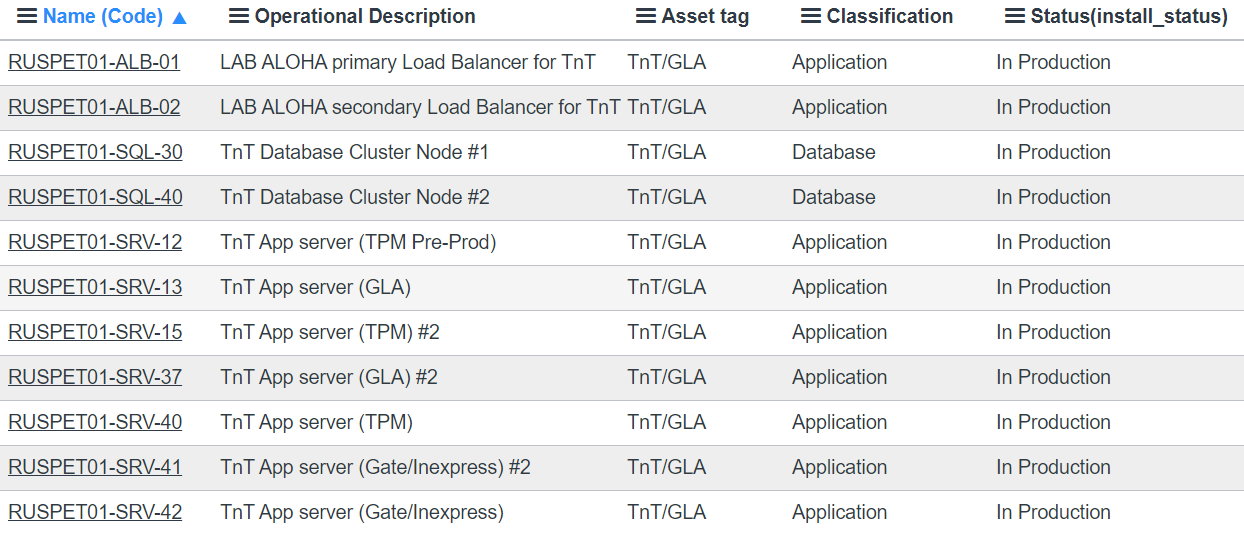
You may generate a report based on the Servers table with Asset Tag equal to T&T/GLA. Here is an example. This report can be filtered by location in order to check existing components for a specific factory.
7.2 Maintenance
7.2.1 Planned Hardware Maintenance
As it was already mentioned the HCI hardware maintenance is performed regularly by DCO and ITSD teams. The maintenance is performed in accordance with JTI standards and is based on recommendations from Microsoft and TA.
The planned maintenance for Hardware components is not causing any downtime to the services and virtual machines. This is always being performed online.
7.2.2 Regular Maintenance for Virtual Machines
As all VMs in the JTI environment, T&T VMs also require regular patching. However, unlike hardware maintenance, the patching activity to VMs is involving an outage during the respective VM patching process.
According to JTI standards each server should be patched on a monthly basis during a selected time frame on a specific day of a specific week. Time for patching application servers should be at least 4 hours (this includes patching, server reboot and recovery of services in case of accidental failure after patching).
For T&T SQL servers the patching is done in accordance with a special schedule:
-
3 hours (at least) for patching secondary (inactive) SQL server node and checking its services;
-
1 hour for failover between active and inactive SQL server nodes (this is when the outage is applied);
-
3 hours (at least) for patching the former active server which becomes inactive. Next month the cycle is repeated.
Based on the above, each factory should provide a time window of 4-6 hours (depending on the amount of servers being patched simultaneously) on a monthly basis preferably week 3 or week 4.
8 Data Retention
Data retention period is vary based on system and should meet values from below table.
| System | Retention period | Hot Storage | Cold Storage |
|---|---|---|---|
| Gate | 18 months | Hot storage only | No cold storage |
| GLA | 18 months | Hot storage 6 months | Cold storage after 6 months up to 18 months |
| InexPress | 1 month | Hot storage only | |
| Corporate Repository | 5 years | ||
| iTrack | 5 years | Hot storage 2 years | Cold storage after 2 years up to 5 years |
| Liz | Not required | Not required | Not required |
| Movilizer Cloud | 36 months | Hot storage 6 months | Cold storage after 6 months up to 36 months |
| Movilizer Scanner | Not required | Not required | Not required |
| TPM | 36 months | Hot storage 6 months | Cold storage after 6 months up to 36 months |
| PR Check Tool | 18 months | Hot storage 12 months | Cold storage after 12 months up to 18 months |
| SAP | Not in T&T scope | Not in T&T scope | Not in T&T scope |
| FractureCode Reader | 36 months | Hot storage 6 months | Cold storage after 6 months up to 36 months |
| Vault | 18 months | 12 months | Cold storage after 12 months up to 18 months |
| iTrack Middleware | Not required | Not required | Not required |
For FractureCode TPM and FractureCode Reader software the data should be uploaded to cloud storage to enable factories to create reports where all the production relevant data is put in context:
-
T&T production data
-
T&T line signals and events
-
FMS data
-
Quality data
-
Qsense data
-
Etc.
Because of this requirement, the cold storage retention for FractureCode related data should be 36 months.
9 Document control
9.1 Contact Person
Questions and feedback regarding this standard should be submitted to the BTS T&T Director.
9.2 Revision
The document will be reviewed by all stakeholders every 18 months. The review will be initiated by the document owner.
9.3 Revision History
| Version | Effective date | Purpose of change | Author |
|---|---|---|---|
| 1 | 01-Oct-2021 | First version of the document | Andrei Dohotaru |
9.4 Sign-off
| Name | Title | Function | Signoff Date |
|---|---|---|---|
| Igor Kharin | GSC Compliance Projects Director | GSC Compliance Projects | |
| Sergey Khitrin | BTS T&T Service Director | IT BTS T&T | |
| Avni Cengel | GDC T&T Delivery Center Director | IT T&T Delivery Center | |
| Xavier Geillon | DC Technical Integration Director | IT Data Center Technical Integration | 15/09/2021 |
| Jose Angel Alonso | Data Center Service Delivery Director | IT Data Centers Service Delivery | |
| Alexey Kinebas | Data Center Technical Architecture Director | IT Data Center Technical Architecture | |
| Erdinc Betin | Network & Communication Center Director | IT Network & Communication Center | |
| Elmar Schloeder | Process Control & Digital Tech. Director | Global Engineering Process Control | |
| Stefan Alboi-Sandru | Regional Factory IT Director WE, EE & AM | Regional Factory IT WE, EE & Americas | |
| Yevgen Golubev | Regional Factory IT Director Asia & MENEAT | Regional Factory IT Asia |
10 References
10.1 JTI IT policies and standards
10.2 JTI GSC Global Engineering policies and standards
ANY QUESTIONS?